Rigid Flex Circuits Be Recycled
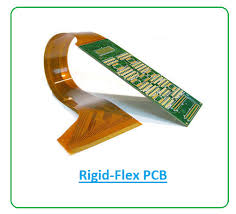
Rigid flex circuits are used in many electronic devices, especially those that require both flexibility and rigid support structures. The flexibility allows for connections in tight spaces while the rigidity provides the structure needed to keep components from moving or shifting during assembly, reflow soldering and other processing steps. They’re often used in consumer electronics, automotive products and medical equipment, as well as military or aerospace hardware due to their reliability and durability under harsh conditions.
Compared to other PCB designs, rigid flex circuits have more complicated layouts and layer counts. This can make them more expensive to fabricate. However, manufacturers can reduce costs by avoiding unique materials, minimizing the number of flexible layers and by utilizing the rigid areas as connections to other PCBs in their design. They can also save on installation costs by eliminating the need for additional connectors and wire assemblies.
Rigid-flex circuit boards can be fabricated using various materials, including FR-4 and polyimide. Depending on the application, manufacturers may choose to use different stiffeners to prevent warping of the flexible sections. In addition, the layout of rigid and flexible sections needs to be carefully considered to reduce component count and avoid excess copper.
Can Rigid Flex Circuits Be Recycled?
The cost of a rigid-flex printed circuit board will depend on the amount of rigid and flexible area that is required. The design of the circuit will also impact the fabrication costs. There are many factors to consider when comparing the cost of rigid-flex circuit boards to other types of printed circuit boards. For example, if the circuit is designed to be flexible, it will need to have a high current-carrying capacity. The higher the current-carrying capacity, the more expensive the circuit will be to fabricate.
A good rigid-flex PCB manufacturer can offer manufacturers cost savings that can offset the initial investment in the design and production of the circuit. Some of these cost savings include fewer reworking and testing times, fewer rejects, less wire routing errors and lower assembly costs. These benefits can be especially significant in the case of long production runs for a specific application.
While the initial investment for a rigid-flex circuit board is typically more than that of a standard PCB, manufacturers can often minimize costs by working with a qualified rigid-flex manufacturer and by following guidelines to optimize the design. This can be done by setting goals for optimization, researching design standards, selecting a rigid-flex manufacturer early in the project and building prototypes to verify that the design meets performance, manufacturability and cost targets.
Once a design has been optimized, the final product will require lamination of the rigid and flexible sections. This process is called “blanking.” The blanked flex section is affixed to a rigid board, usually made of FR-4 or polyimide material, with copper-plated vias connecting the flex circuit to the rigid sections. This will allow for a more durable and reliable final assembly. During the lamination process, the flex circuit will be pre-etched and cut to ensure proper alignment. The etch and cut will then be bonded to the rigid panels using an adhesive, and the final assembly panel will be routed with the appropriate holes for mounting.